Leveraging 3D Concept Design for Aircraft Interiors: Turning Ideas into Certifiable, Buildable Monuments
In cabin programs, speed is nothing without certainty. Airlines want faster refresh cycles, OEMs want tighter integration, and regulators demand airtight compliance. The pressure falls squarely on the interior “monuments”—galleys, lavatories, closets, seat monuments, stowage bins, purser workstations, doghouses—because they concentrate structural load paths, systems interfaces, human factors, and certification risk.
This is where 3D concept design earns its keep. Done well, it compresses decision latency, de-risks certification, and shortens the distance between a good idea and a shipset delivered on time. Done poorly, it becomes another glossy model that breaks at the first clash check or linefit gate.
Below is a practical view of how to deploy 3D concept design for aircraft interior monuments to maximize program certainty, not just aesthetics.
What “3D Concept Design” Really Means (And What It Isn’t)
3D concept design is more than styling or early CAD. It’s a structured, model-driven process that connects layout of passenger accommodations (LOPA), human factors, systems integration, manufacturability, and certification evidence along with engineering requirement of weight optimization, functional clarity, positional fitment and ease of maintenance ensure durability —from the first week of ideation.
A strong 3D concept model should:
- Anchor to LOPA and aircraft station references (Fuselage Station/Waterline/Butt line), not just a visual sketch.
- Carry interface contracts (mounting rails, frames, floor tracks, intercoastal /overhead geometries) from day one.
- Include envelope reservations for systems: potable/grey water, air distribution, drains, waste, wiring, antennas, and smoke detection.
- Encode regulatory constraints (e.g., 16g dynamic loads, 25.853 flammability, HIC, emergency egress widths, accessibility) as parametric rules, not post-hoc checks.
- Provide manufacturing realism: draft angles, joinery philosophies, access panels, fastener strategies, and realistic material thicknesses.
Think of the concept model as a pre-IFC “digital contract” that disciplines creative choices with engineering facts—so the team doesn’t re-negotiate physics later.
Why Monuments Are the Prime Candidates
Monuments are multi-disciplinary choke points. A lavatory, for instance, blends water, waste, electrical, ventilation, structure, lighting, doors/locks, and composites within a tight regulatory envelope. Galleys add galley insert equipment (GIE), catering trolleys, power management, and burn certification complexity. Stowage’s and closets must meet crashworthiness and retention requirements while preserving aisle widths and crew flows.
3D concept design unlocks value here because:
- Early clash detection prevents hard rework with frames, stringers, ducts, or harnesses.
- Human-factors validation (95th/5th percentile reach, sightlines, crew choreography) can be simulated instead of guessed.
- Weight & CG discipline begins early, preventing late surprises to payload/range.
- Supplier co-design becomes practical—GIE vendors, door manufacturers, or insert suppliers can validate interfaces against a shared model.
- Load distribution ensures thru IFL within OEM allowed design load.
- Structural validation provides early strength criticality, stability and optimized weight.
A Proven Workflow for 3D Concept Design of Interior Monuments
1) Define the Mission—and Lock the Boundaries
- Airline business intent: Increased galley service life and speed? Extra revenue stowage? Accessible lav? Premium cabin differentiation?
- Hard constraints: Frame stations, floor track positions, PSU and overhead vaults, egress corridors, LOPA adjacency, and weight budgets.
- Reg & safety must-haves: 25.561/562 loads, 25.785 seating/occupant protection, 25.853 flammability, smoke detection/containment, and accessibility requirements specific to airline/region.
Decision checkpoint: a one-page “Monument Charter” that lists what will not change.
2) Parametric Concept Modelling
- Build a parametric skeleton with driver dimensions (height/width/depth, door swings, service clearances, maintenance access zones, trolley footprints).
- Attach rule sets for minimum aisle widths, egress paths, HIC zones, and service envelopes.
- Pre-bake mounting and load paths (e.g., seat-track interface, frame tie-ins, bracket families) so structural intent is inherent.
Outcome: a concept model that “knows” when a creative change breaches a rule.
3) Human Factors & Operations in the Loop
- Insert digital mannequins (5th percentile female to 95th percentile male) to validate reach envelopes, sightlines, and task sequences.
- Run service choreography (e.g., trolley extraction, door swings, water service, waste removal) to avoid dead-ends and collisions.
- Stress-test cleaning and maintenance access—often the biggest operational pain point post-entry-into-service.
Outcome: design choices that defend both passenger experience and crew efficiency.
4) Systems and Structural Pre-Integration
- Allocate routing corridors for water, waste, ventilation, power, and data before “surface beauty.”
- Define structural joinery: ribs, shelves, and hard-points that translate into predictable 16g performance.
- Reserve COTS equipment volumes (ovens, chillers, boilers, water heaters, pumps, HEPA) as true geometry, not wireframes.
Outcome: concept models that survive the first serious interface review.
5) Material & Manufacturing Realism
- Select a reference bill of materials early: phenolic honeycomb, thermoplastics, aluminum extrusions, CFRP panels, edge-closeouts.
- Model drafts, radii, flange widths, insert spacing, and realistic panel thickness.
- Anticipate burn test strategies (OSU heat release, smoke density, vertical burn) to avoid late material substitutions.
Outcome: a concept that can be quoted and tooled.
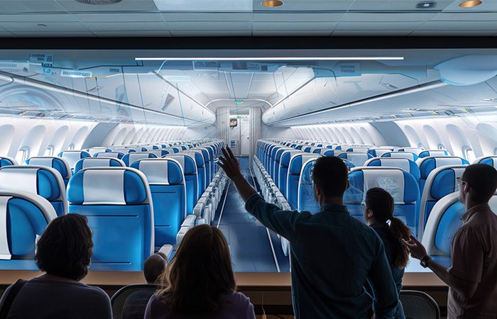
6) Validation through Digital Mock-Up (DMU) & AR/VR
- Place the monument into the full aircraft DMU to check clashes, maintenance envelopes, and evacuation lines across cabins.
- Use VR reviews with crew and cert reps; capture punch-list items with timestamps and geometry IDs.
- Run change impact analysis automatically: a 5 mm panel increase shouldn’t ripple unchecked through doors, bins, and PSU.
Outcome: fewer change orders, faster buy-offs at each gate.
Metrics That Matter (and Prove the ROI)
Executives should track a short, ruthless dashboard:
- Concept-to-IFC change orders (COs): Aim for >40–60% reduction vs. historical baselines.
- First-pass interface approval: Target >90% on earliest integration gate.
- Service choreography time: Seconds saved per cycle in galley/lav tasks translate to real block-time efficiency.
- Weight & CG adherence: Variance from concept target at PDR/CDR.
- Certification test rework: Fewer retests on 25.853 and 16g indicates concept model fidelity.
- Supplier lead-time compression: Weeks saved by providing manufacturable geometry and stable interface definitions.
Common Failure Modes—and How to Avoid Them
- “Pretty but physics-free” models: Solve with parametric rules, structural intent, and systems placeholders from day one.
- Late human-factors review: If ergonomics is a slide-deck, you’re late. Bring mannequins into the concept model.
- Interface sprawl: Freeze interface contracts (mounting, power, data, ducts, drains) at concept gate; change only by exception.
- Material wish-casting: Lock an initial material stack and burn-test plan early; treat changes as costed engineering decisions.
- Disconnected suppliers: Co-design in the shared DMU; mandate neutral CAD and STEP exchanges with versioned interface control documents (ICDs).
Sustainability and Maintainability—Designed In, Not Bolted On
3D concept design can systematically pursue weight reduction (panel cores, optimized ribs), repairability (snap-fit access panels, standardized inserts), and end-of-life (mono-material strategies where possible). Designing service access into the 3D concept—filter replacements, valve access, latch service—pays back in airline satisfaction scores and reduced AOG risk.
TAAL Tech: From 3D Concept to Certifiable, Buildable Monuments
TAAL Tech has supported OEMs, Tier-1s, and MROs on concept-to-delivery for interior monuments across narrow- and wide-body platforms. Our approach blends parametric 3D concepting, DMU integration, and cert-aware engineering to shorten cycles and raise confidence at every gate.
What we do for monument programs
- 3D Concept & DMU: Parametric monuments anchored to LOPA and frame stations; early envelope checks across PSU, bins, and systems.
- Human Factors & Ops: Digital mannequins, service choreography, cleaning/maintenance accessibility simulations.
- Systems & Structure: Pre-routed corridors for water/waste/HVAC/electrical; load-path intent for 14 CFR part 25 emergency load compliance; bracket families and track-mount strategies.
- Material & Burn Strategy: Early BOM definition, draft/detailing realism, and 25.853 planning to avoid late material churn.
- Supplier Co-Design: Interface control documents, neutral CAD exchanges, and rapid iteration with GIE and door/insert suppliers.
- Certification Support: Evidence packages for loads, flammability, and HIC; change impact analyses; conformity readiness.
Typical outcomes we target
- 40–60% fewer design COs between concept and IFC
- Weeks shaved off GIE integration due to stable interface definitions
- Higher first-pass approvals at PDR/CDR and smoother conformity
If you’re planning a cabin refresh or a new-build linefit and want certainty without sacrificing creativity, a disciplined 3D concept design flow is your fastest path to a certifiable, buildable monument set—and an interior your passengers and crews will love.
The best cabin programs don’t “hope” their monuments will fit, function, and certify; they prove it in the concept model—using rules, physics, and rehearsal. That is the promise of 3D concept design: fewer surprises, faster gates, and an interior product that meets business intent on the first try.
Abbreviation –
IFL – Interface load
IFC – in flight control
PDR – Preliminary design review
CDR – Critical design review
HIC – Head Injury Criteria
GIE – Government-Installed Equipment
COTS – Commercial Off-The-Shelf solution


