
18
August, 2026
Factory Layout Design: Finding Production Bottlenecks Before Capital Is Committed
Airlines are having to extract more value from aircraft already in service. In June 2026, IATA reported that the global aircraft order A production line can meet every equipment specification and still miss its output target. The machines may be fast enough, yet operators wait for parts, forklifts cross assembly routes, buffers overflow and inspection becomes the real constraint. Once the floor is built, correcting these problems is expensive.
Factory layout design allows manufacturers to test flow, capacity, access and safety before capital is locked into concrete, utilities and equipment positions.
A Layout Is a Production Decision, Not a Drawing Exercise
Factory layouts are often reviewed as arrangements of machines, aisles and storage zones. That view is incomplete.
The location of each resource influences how far material travels, where work-in-progress accumulates, how operators move and which processes compete for shared equipment. The real question is whether the proposed arrangement can deliver the required product mix at the expected takt time.
Research has long treated facility layout as a major manufacturing cost problem. Studies cited in facility-planning literature indicate that an effective layout can reduce material-handling costs by 10% to 30%. A 2025 stamping-workshop study reported a 25.01% reduction in logistics-handling costs after optimizing equipment placement. These results are not guarantees for every plant, but they show how much cost can remain hidden in movement rather than machining or assembly.
How a Logical Line Can Still Underperform
Consider a manufacturer planning an assembly line for several product variants. On a 2D drawing, the stations follow the correct order, the line looks compact and every asset fits.
During operation, however, the variants do not move through the factory identically. One requires an additional test. Another uses a component stored at the far end of the building. A shared crane serves both assembly and rework. Empty pallets return through the inbound-material aisle.
Small delays begin to combine:
- Operators leave their stations to collect parts.
- Forklifts wait at narrow intersections.
- Finished assemblies block the test area.
- Rework moves against normal production flow.
- The crane becomes unavailable during peak periods.
A faster assembly machine will not solve this. The constraint sits in the relationships between stations, people, storage, handling systems and production rules.
Start with Demand, Product Mix and Process Logic
Factory layout planning should begin with what the facility must produce, not with the building footprint.
Annual volume alone is insufficient. Engineers also need product mix, batch sizes, routing differences, changeover frequency, shift patterns, rework loops, replenishment methods and expected growth. A layout designed around average demand can fail during a realistic peak.
Suppose two products use the same welding cell. Product A needs six minutes, while Product B needs eleven. A blended average may suggest that the cell has enough capacity. A simulation using the actual sequence may reveal queues whenever several Product B units arrive together.
This is why line balancing and layout development must proceed together. The arrangement determines travel and access, while process times determine how work accumulates within it.
Map Every Movement, Including the Ones That Add No Value
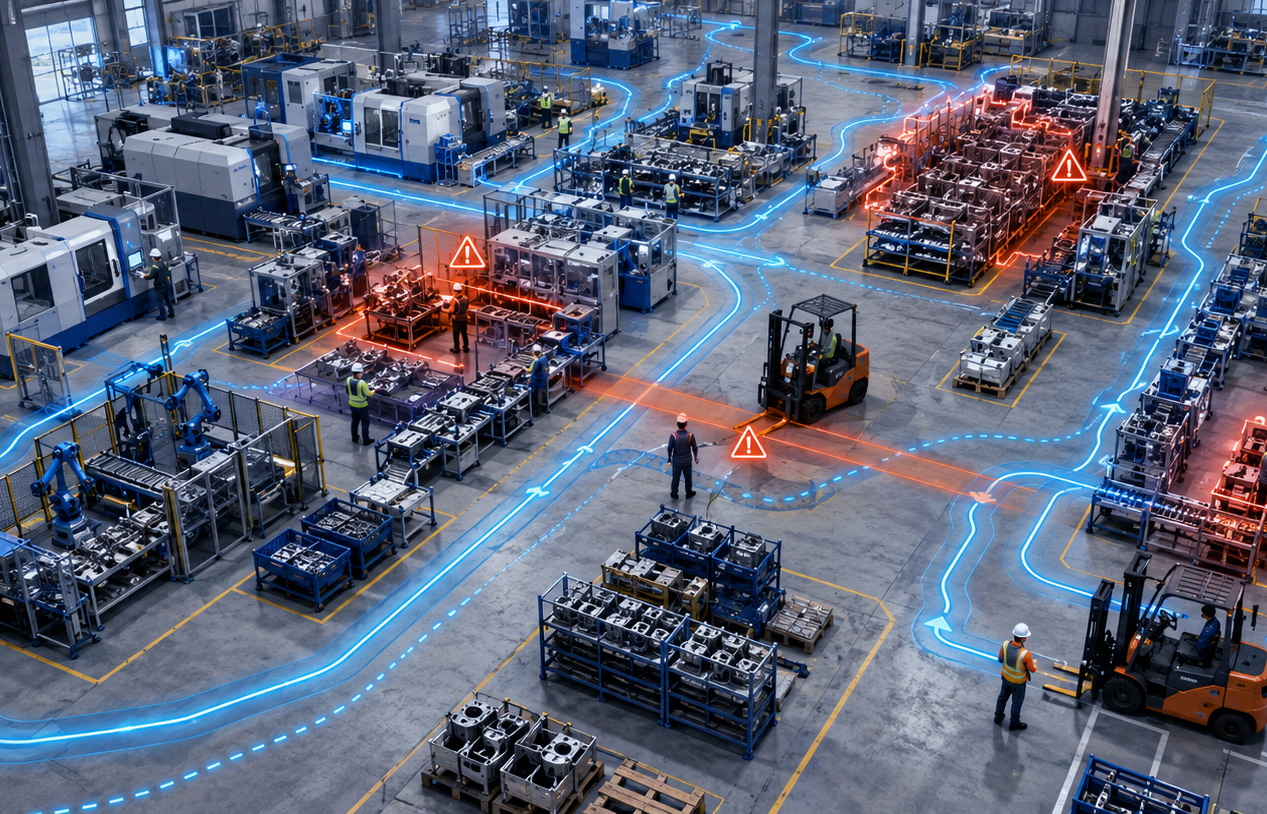
Material flow analysis should follow raw materials, components, tools, containers, finished goods, scrap and rework. It should also include people and vehicles.
A part may undergo four value-adding operations but be handled twelve times. It may be unloaded, staged, stored, issued to a supermarket, delivered to the line, returned after inspection and moved again for packing. Each transfer adds time, space, handling demand and damage risk.
A useful flow study asks:
- How many trips occur between each pair of areas?
- Which routes cross, reverse or create waiting?
- Where does work-in-progress accumulate?
- Which movements increase during a changeover or disruption?
- What load and handling method apply to each trip?
NIST’s factory-design framework treats layout, capacity and material-flow analysis as connected activities rather than separate checks. Its factory-improvement model covers both new facilities and modifications to operating plants.
A shorter route is not automatically better if it creates congestion, compromises access or feeds a process faster than the next station can absorb work.
Use Simulation to Test the Factory Before It Exists
Static calculations can estimate capacity under steady conditions. Real production rarely remains steady.
Machines fail. Operators take breaks. Components arrive late. Products follow different routings. Changeovers consume time. Rework returns to earlier stages. Simulation helps teams examine how these variations interact over a shift or production campaign.
A useful factory simulation can test:
- Throughput under different product mixes
- Queue growth at constrained stations
- Buffer sizes and locations
- Forklift or AGV utilization
- Operator walking and shared-resource demand
- Effects of downtime and changeovers
One 2026 simulation-based optimization study reported a 23% throughput increase, a 31% reduction in material travel time and a 17% decrease in workstation idle time in its evaluated system. The figures belong to that specific case, but the lesson is relevant: layout performance must be tested as a dynamic system, not judged only by visual neatness.
Simulation can also prevent overinvestment. It may show that the target output can be achieved by relocating a buffer, changing replenishment frequency or rebalancing work instead of purchasing another machine.
Plan for Operators, Maintenance and Material Handling
A compact layout can look efficient while creating difficult work.
Operators may need to twist for parts, reach across fixtures or walk around guarding. Maintenance teams may lack space to remove a motor. Forklifts may reverse into pedestrian zones because turning space was sacrificed. These conditions influence safety, cycle-time stability and equipment availability.
OSHA advises that workstations should minimize the distance between the worker and the object being handled. Its materials-handling rules require sufficient clearances for aisles, doorways and turning areas, while its forklift guidance recommends separating pedestrians and vehicles wherever possible.
Three-dimensional layout reviews and virtual validation should check:
- Operator reach, posture and loading access
- Robot and tool reachability
- Equipment-removal and maintenance paths
- Vehicle turning space with actual loads
- Safe pedestrian access to workstations
The objective is not to fit the maximum number of assets into the minimum area. It is to create a production environment that remains usable throughout its operating life.
Design for Change Before Change Becomes Expensive
Many factories are planned around one launch and then expected to support years of product and volume change.
A rigid layout may perform well at the initial forecast but become costly when a new variant needs another test station, automation is added or demand shifts. Flexibility should therefore be evaluated deliberately through modular workstations, accessible service corridors, reconfigurable material routes, reserved utility capacity and alternative demand scenarios.
For a brownfield facility, existing columns, utilities, fire routes and live production restrict what can move. Scan-to-model workflows can establish a reliable three-dimensional baseline, after which teams can compare phased layouts and installation sequences without depending on outdated drawings.
What Decision-Makers Should Review Before Approval
Senior leaders do not need to debate every workstation dimension, but they should ask for evidence that the proposed facility works as an operating system.
Before approving capital, the review should answer:
- Which product-mix and peak-demand scenarios were tested?
- Where is the current constraint, and what becomes the next one?
- How far and how often do materials, operators and vehicles travel?
- What happens when a key machine fails or a component arrives late?
- Are ergonomic, maintenance and safety clearances validated in 3D?
- How will the layout accommodate the next product or volume increase?
- Which assumptions could materially change the investment case?
A layout presentation should therefore include flow paths, capacity assumptions, simulation results, constraint maps, safety reviews and the trade-offs behind the recommended option.
Commit Capital After the Factory Has Been Challenged
Factory layout design is most valuable before equipment locations, pits, foundations and utilities become difficult to change. At that stage, engineers can still compare alternatives, expose hidden constraints and test whether the proposed system achieves its production objective.
TAAL Tech supports manufacturers through 3D factory and virtual concept layouts, greenfield and brownfield facility engineering, material-flow optimization, robotic and process simulation, line balancing, and safety and ergonomic validation. These capabilities connect product and process requirements with the physical factory so investment decisions reflect how production will actually behave, not simply whether every asset fits.